Potential Dividers
- The electrical voltages rule is defined as:
The sum of the e.m.f.s in a closed circuit loop is equal to the sum of the potential differences around that loop
- Therefore, when two resistors are connected in series, the potential difference across the power source will be divided across the two resistors
- Potential dividers are circuits that produce an output voltage as a fraction of the input voltage
- This is done by using two resistors in series to split or divide the voltage of the supply in a chosen ratio
- Potential dividers have three main purposes:
- To provide a variable potential difference
- To enable a specific potential difference to be chosen
- To split the potential difference of a power source between two or more components
- Potential dividers are used widely in volume controls and sensory circuits using LDRs and thermistors
- The link between the input voltage and the output voltage across each resistor is linked in an equation
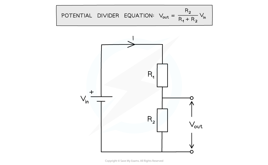
Potential divider diagram and equation
- The input voltage Vin is applied across both resistors, which are in series
- The output voltage Vout is measured across one of the resistors, in this case resistor R2
- The potential difference V across each resistor depends upon its resistance R:
- The resistor with the largest resistance will have the greater potential difference across it
- This is shown as a greater Vout
- This is from V = IR
- If the resistance of one of the resistors is increased, it will get a greater share of the potential difference, whilst the other resistor will get a smaller share
- Since potential divider circuits are based on the ratio of voltage between components, and since V=IR, this is equal to the ratio of the resistances of the resistors
- Therefore, the ratios of the potential differences and resistances across each resistor can be linked

- Where:
- V1 = potential difference of R1 (V)
- V2 = potential difference or R2 (V)
- Using Ohm's Law, with a constant current, I, these can also be written as:
- V1 = IR1
- V2 = IR2
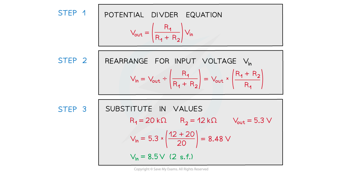
Worked example
The circuit shown is designed to light up a lamp when the input voltage exceeds a preset value.

Vout is equal to 5.3 V when the lamp lights.
Calculate the input voltage Vin.